Background reading on electrostatic headphones. The summary: Stretch charged plastic between metal grids, then put a signal on the grids to attract and repel the plastic. This movement creates sound.
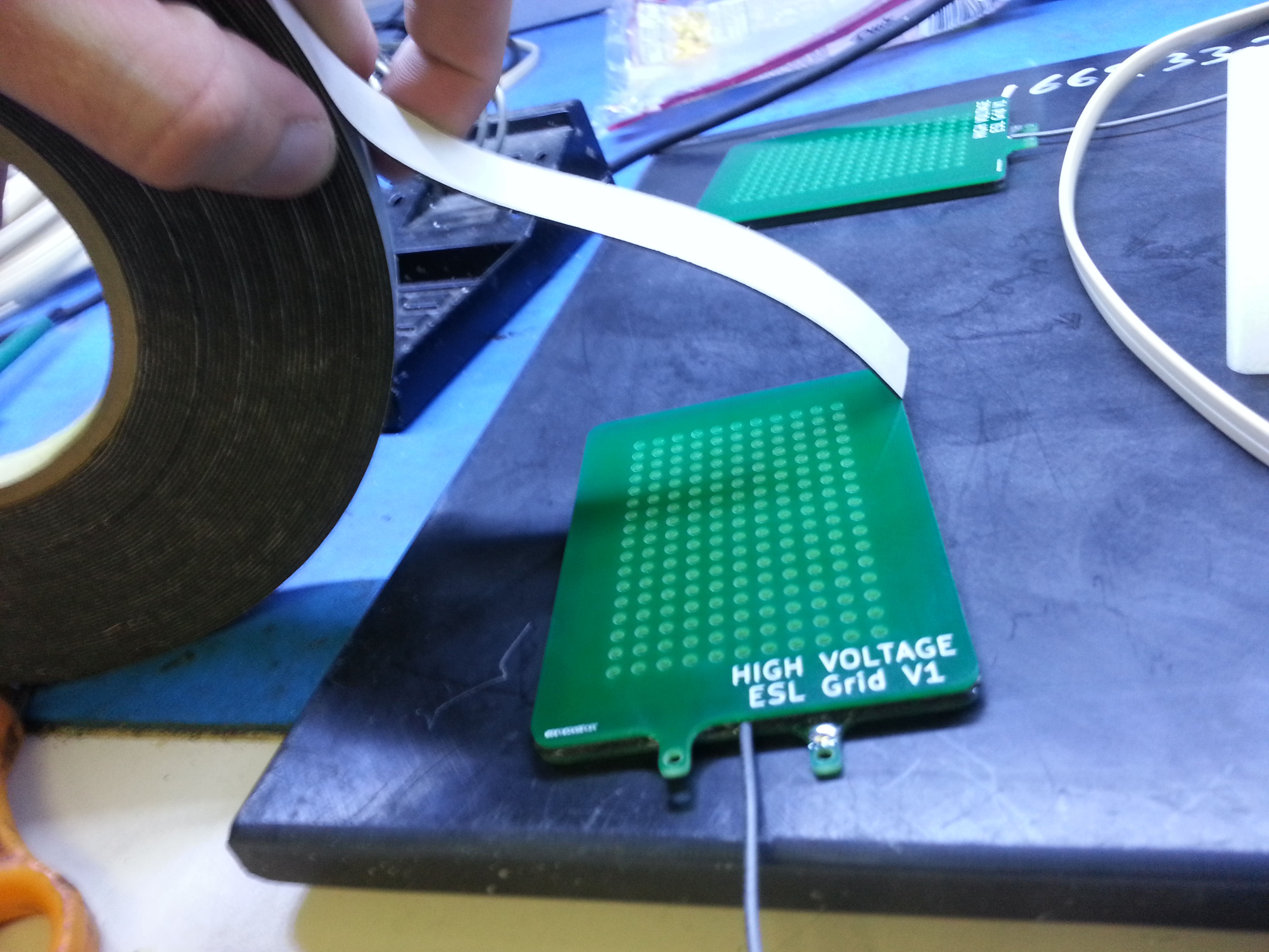
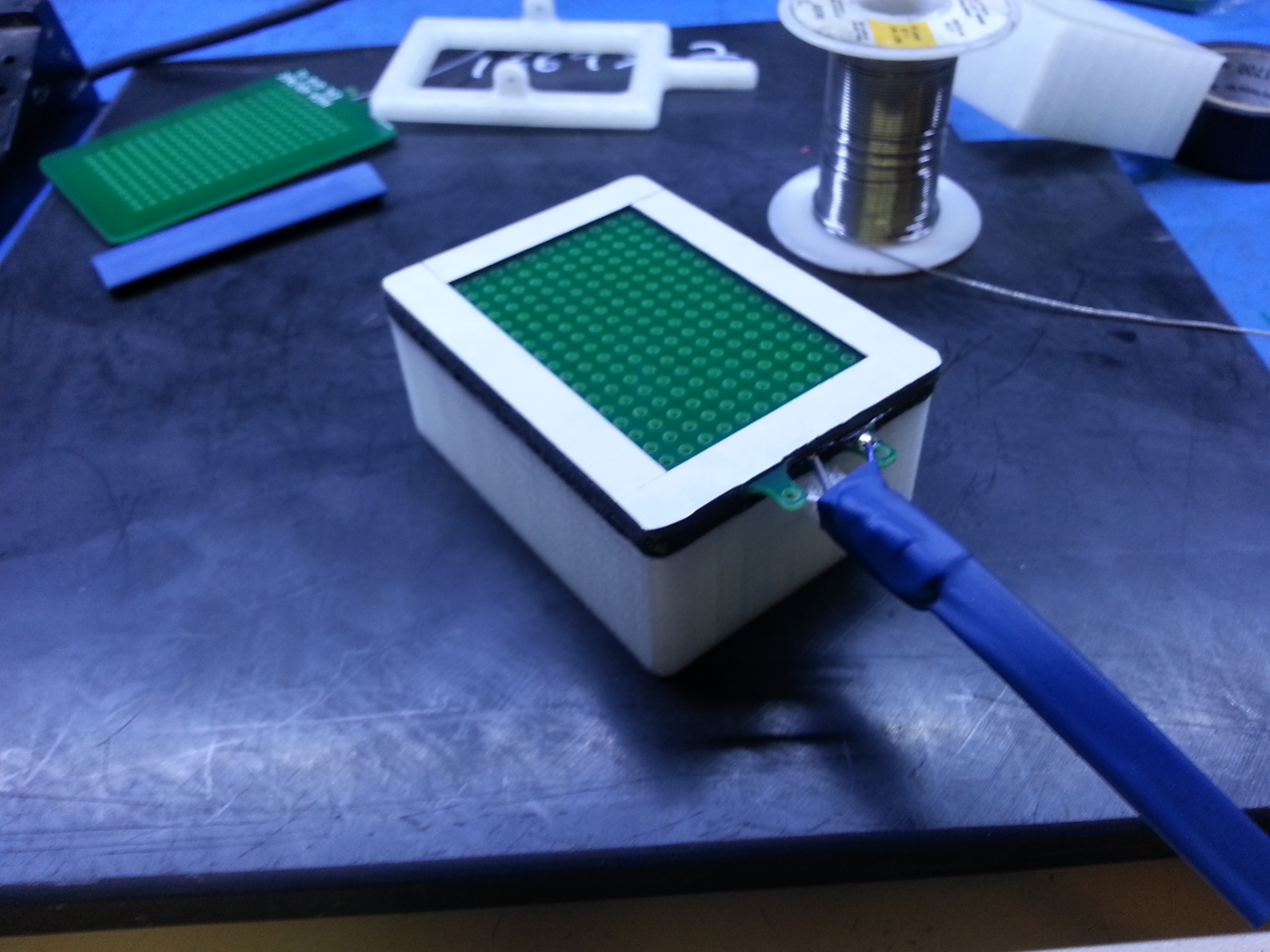
This will be a quick picture story of how I built my own electrostatic headphone prototype. I began by sitting down and designing a PCB (printed circuit board) with a copper grid insulated by solder mask, a boarder for attachment, and a tail for wire management.
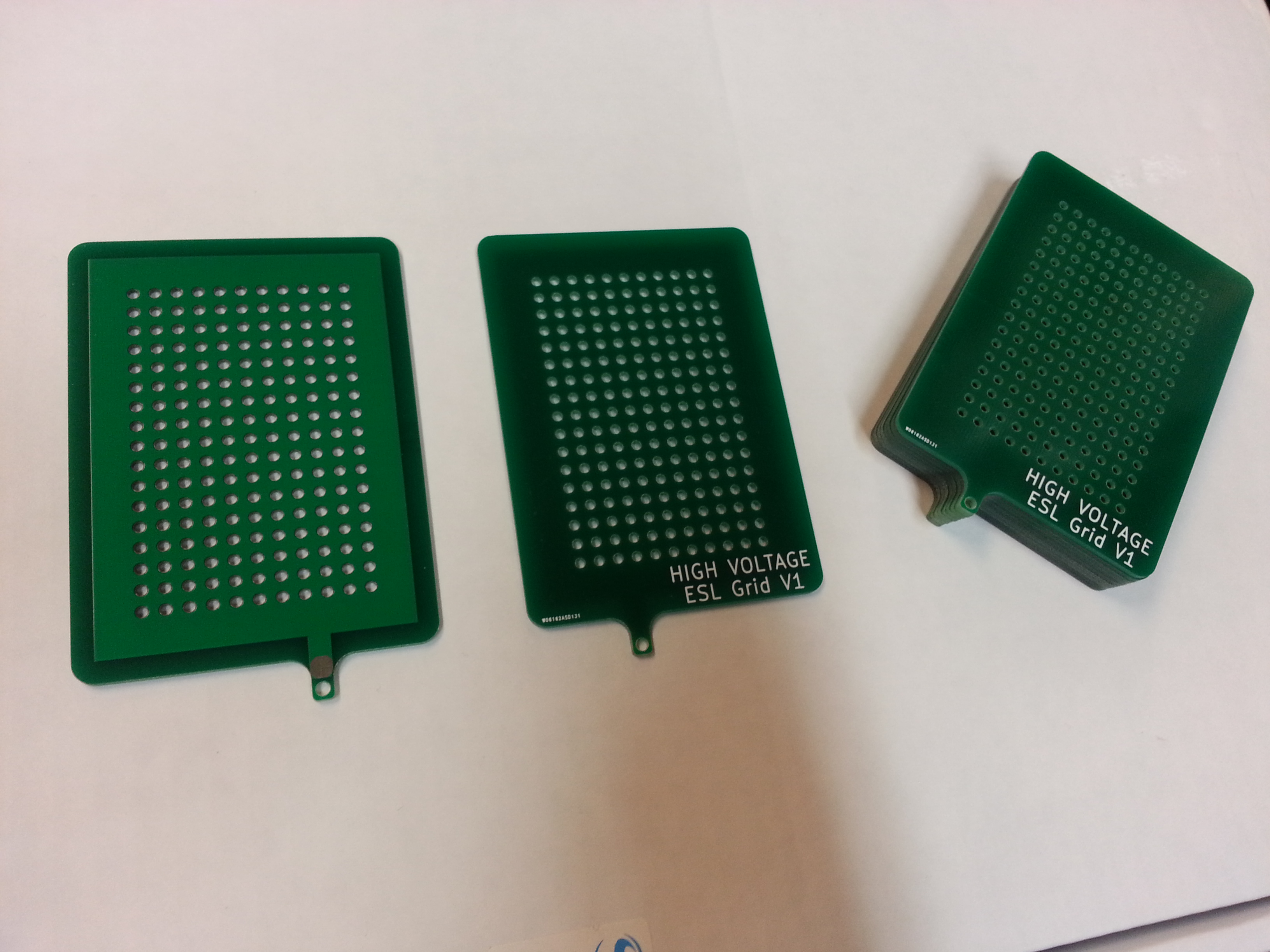
I use 3pcb for making my boards, this stack was only $13. Notice only one side has copper, and the copper is covered by solder mask, which prevents arcs, and hopefully protects my ears!
Next, I needed to add spacing between the grid and the plastic film, and I needed to tension and prepare the plastic film itself. I took the Jazzman (awesome Electrostatic speaker builder, check out his blog) route for spacing: double-sided tape. It gives a slightly larger gap than I would like, however, it’s super quick.
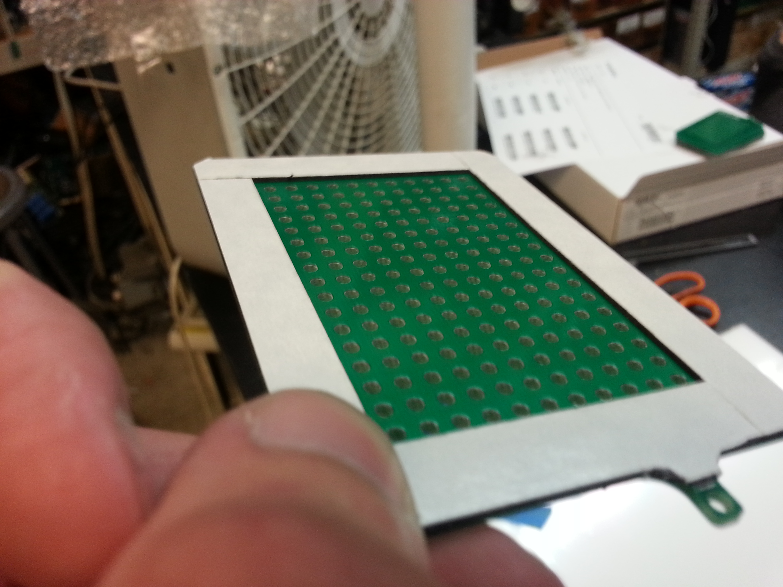
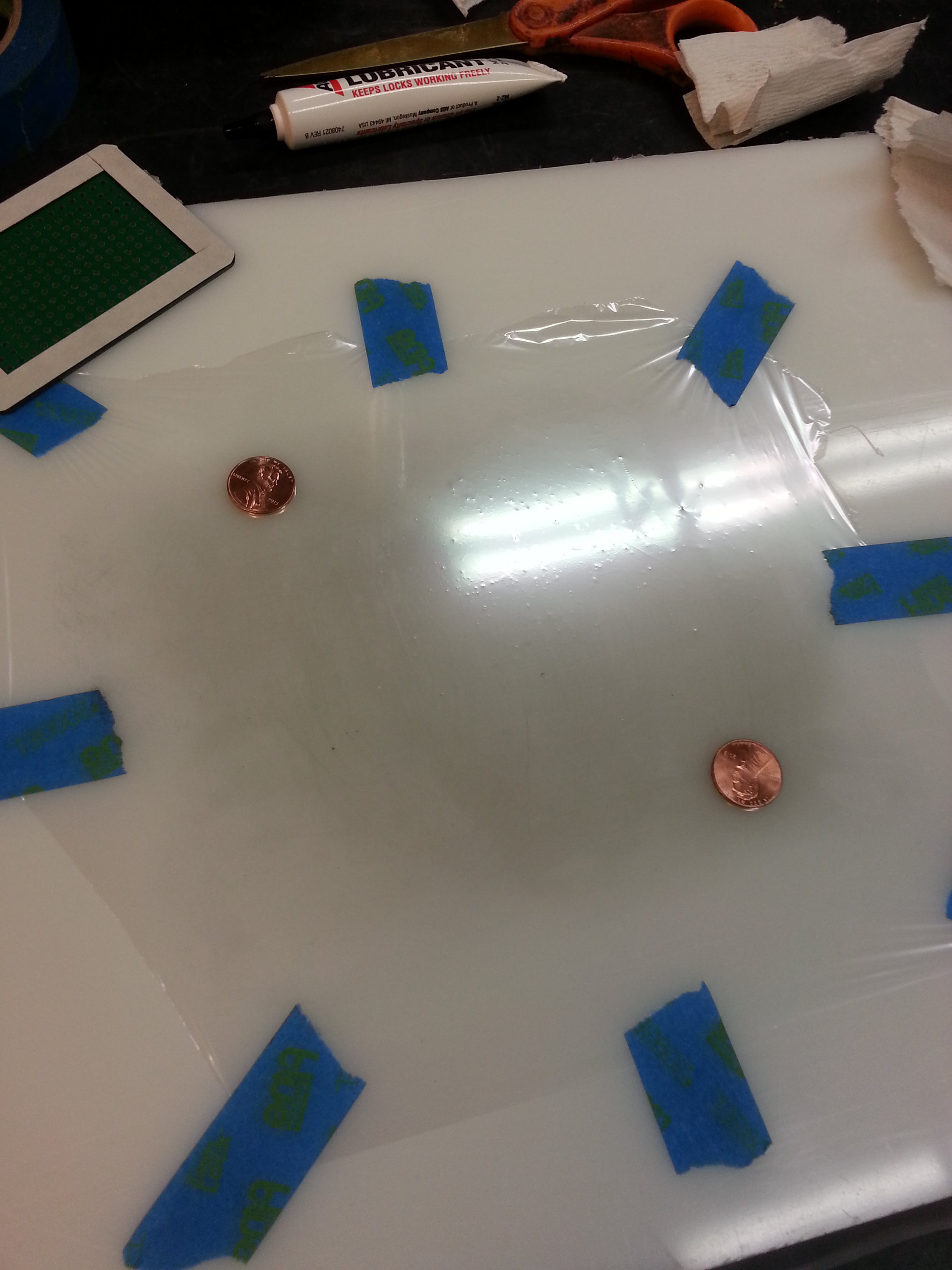
Next, I used masking tape to stretch the incredibly thin Mylar film on a smooth, clean piece of plastic.
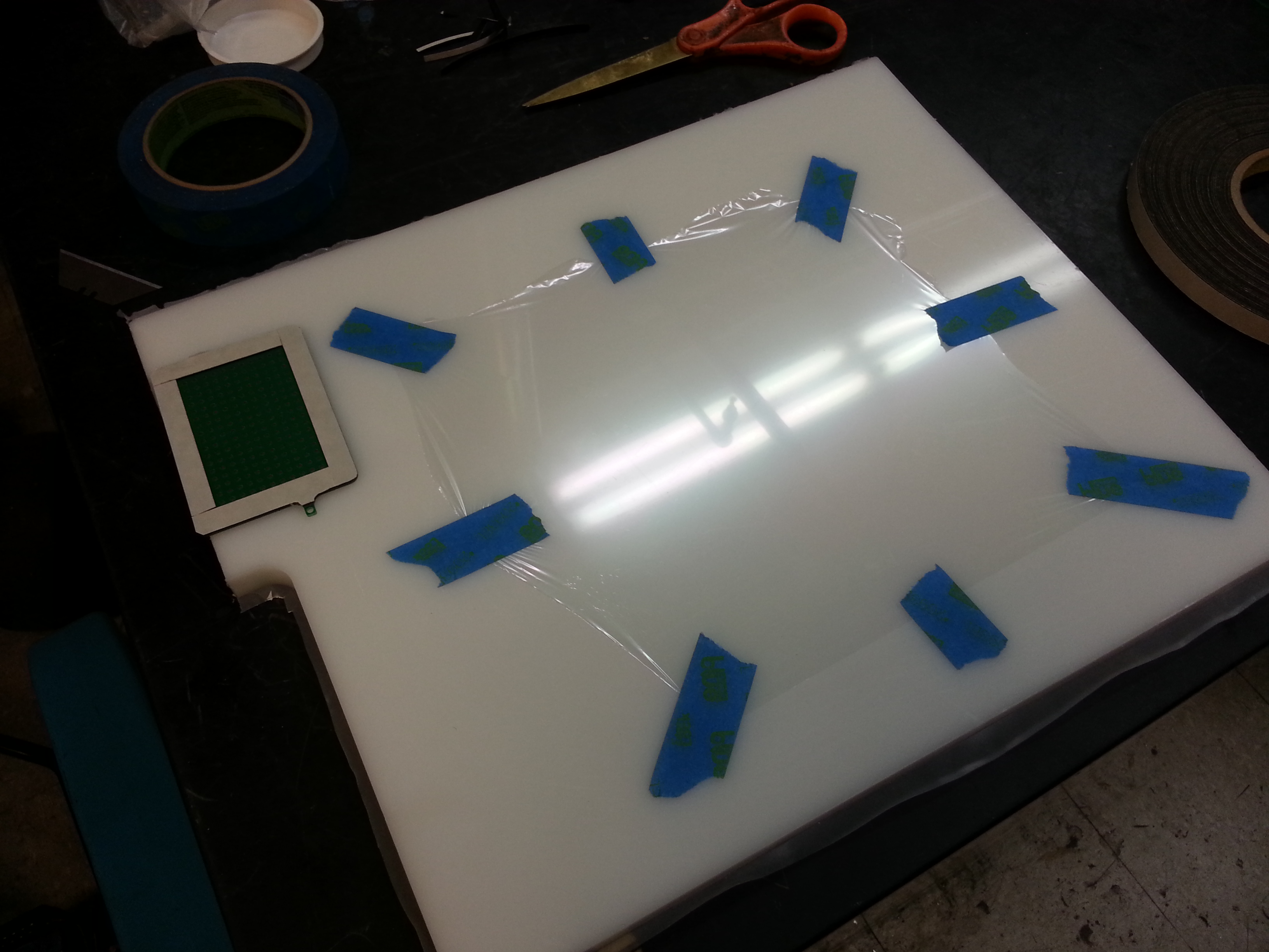
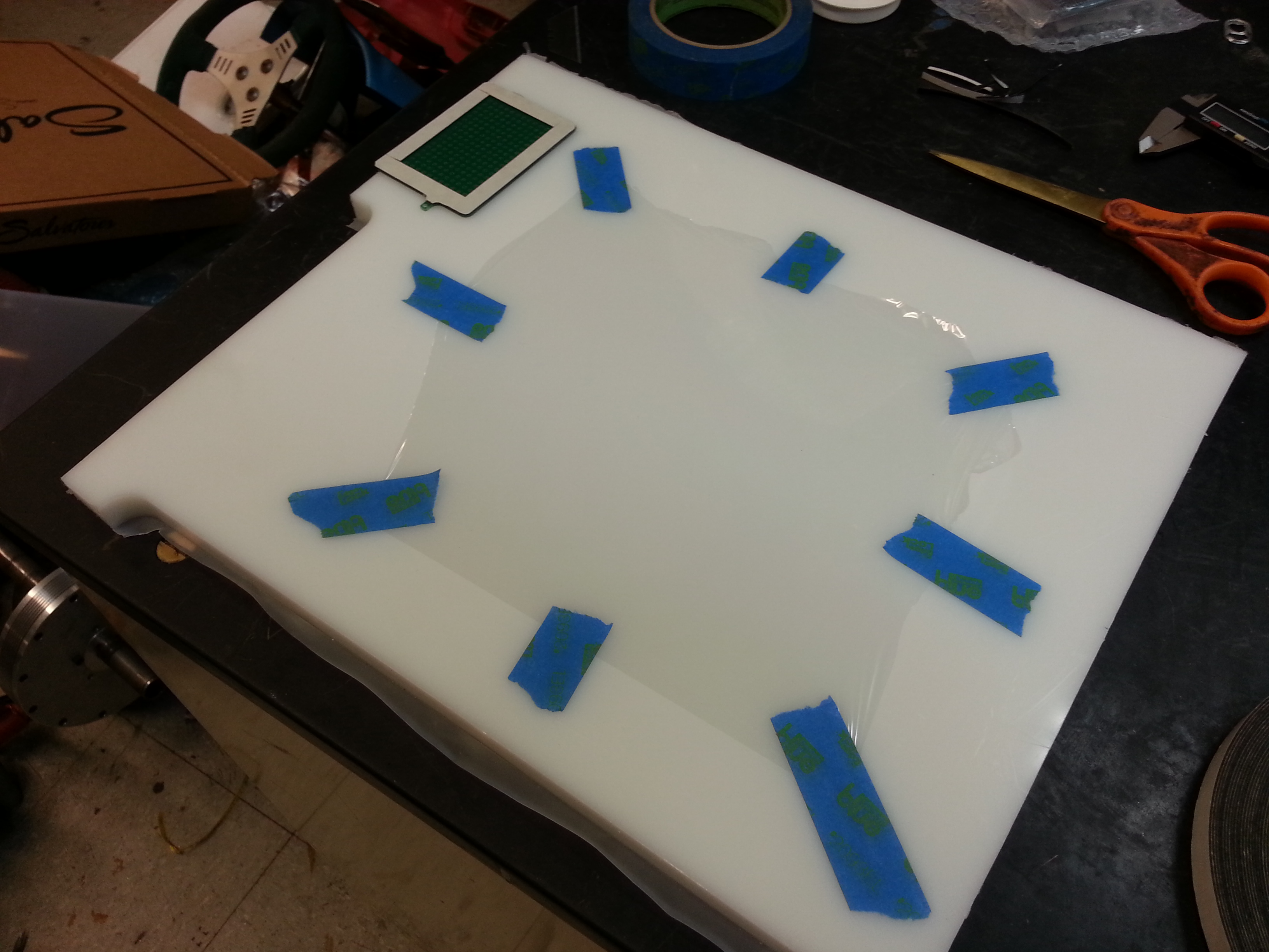
Now I needed to prepare this plastic surface. The plastic sheet needs to be very slightly conductive, so that it can be charged. It also needs to be very high resistance, to limit damage if the plastic arcs to a grid. I used some lock lubricating graphite powder to make the surface conductive. I sprinkled some graphite evenly over the surface, then rubbed it in with some very soft cloth. RUB HARD, you should hardly see any graphite on the finished plastic. The only thing keeping the graphite attached to the Mylar plastic sheet is you smashing it in with the cloth, so seriously press hard.

After the graphite was applied, I checked the conductivity by placing two conductive objects on the surface, and checking the resistance between them.
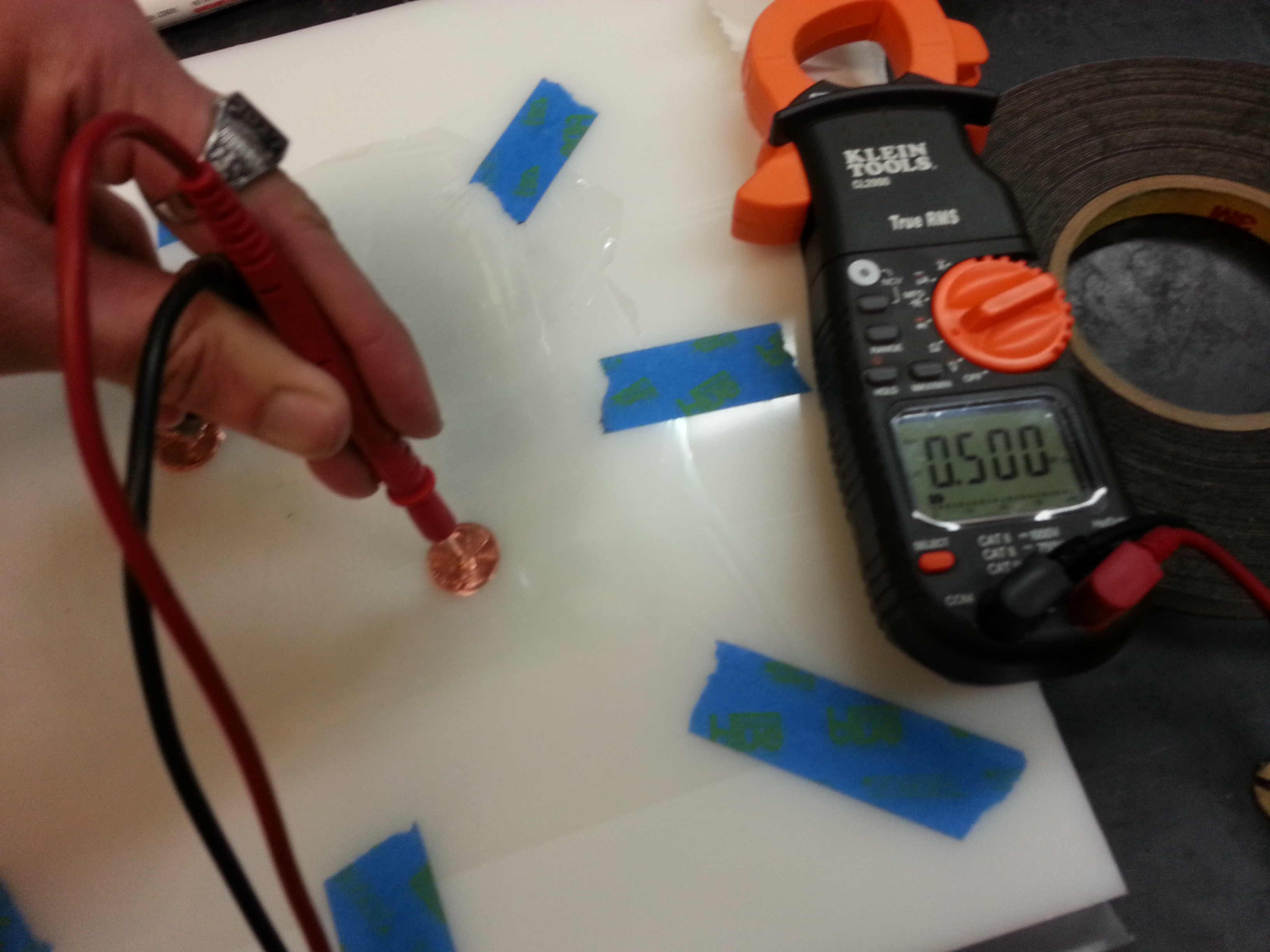
That resistance was on the low side, so I rubbed the surface with clean cloths until the resistance was just higher than my meter could read.
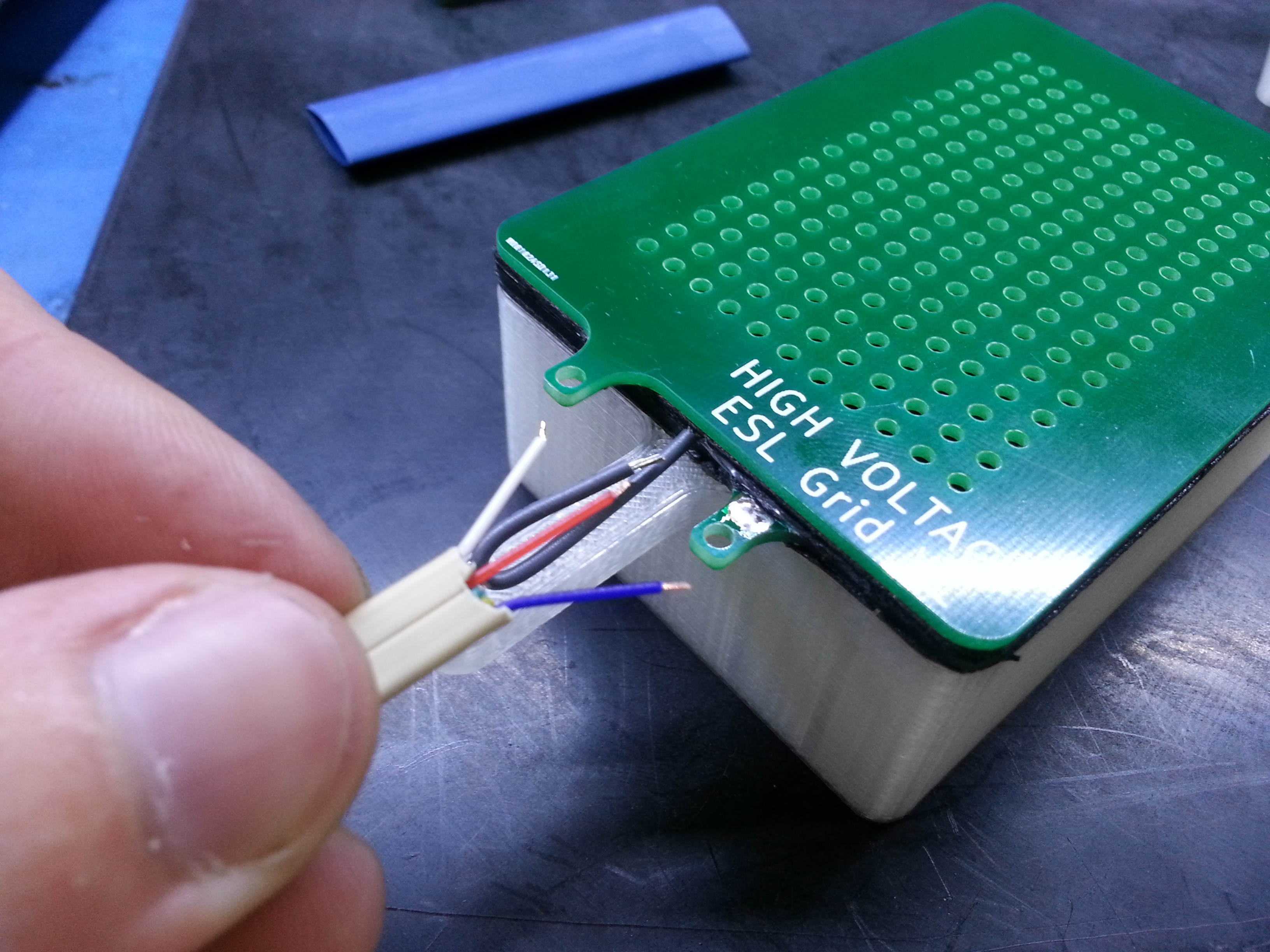
Next, I added some wire to the double-sided tape to make contact with the graphite side of the Mylar film:
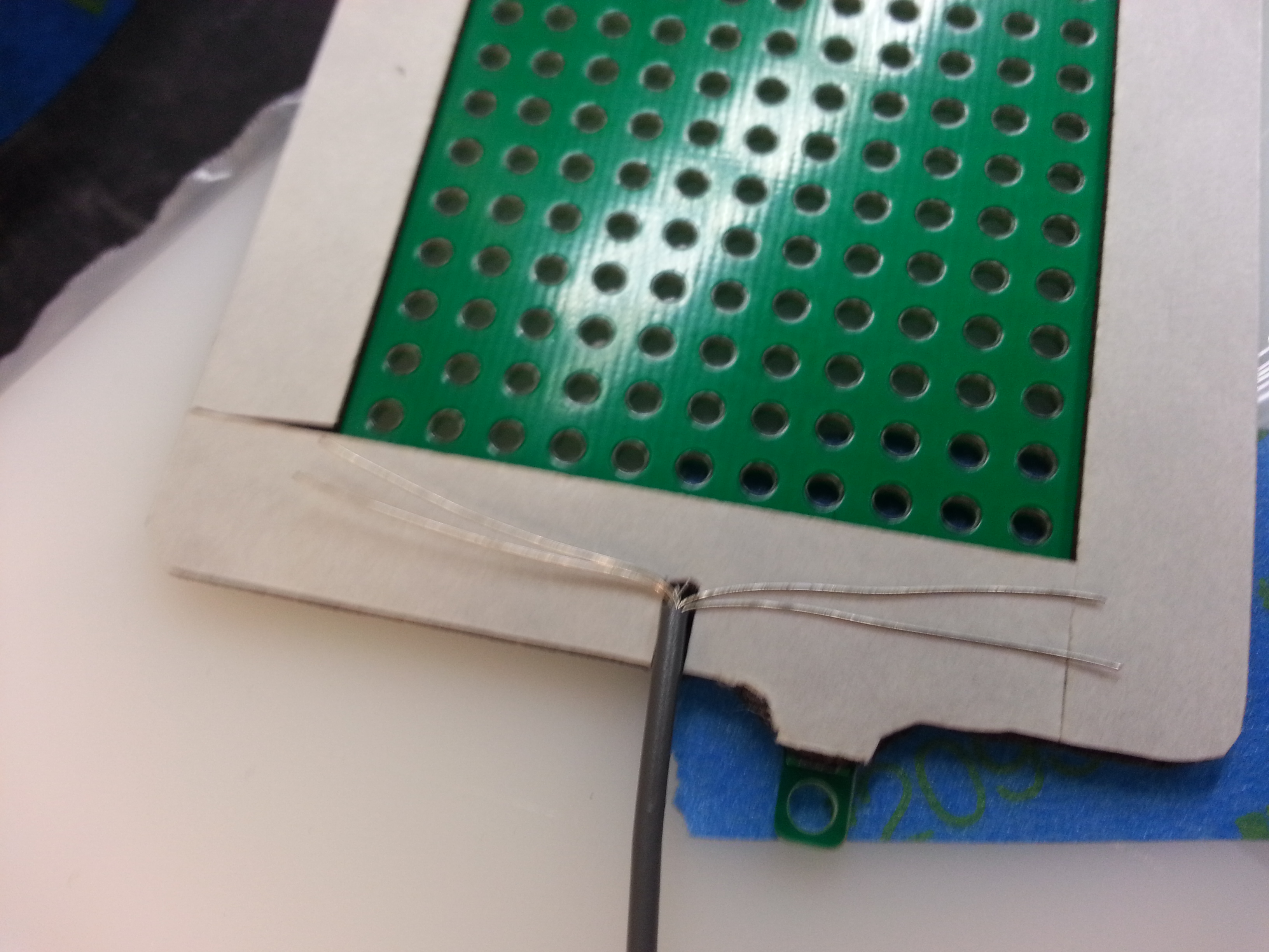
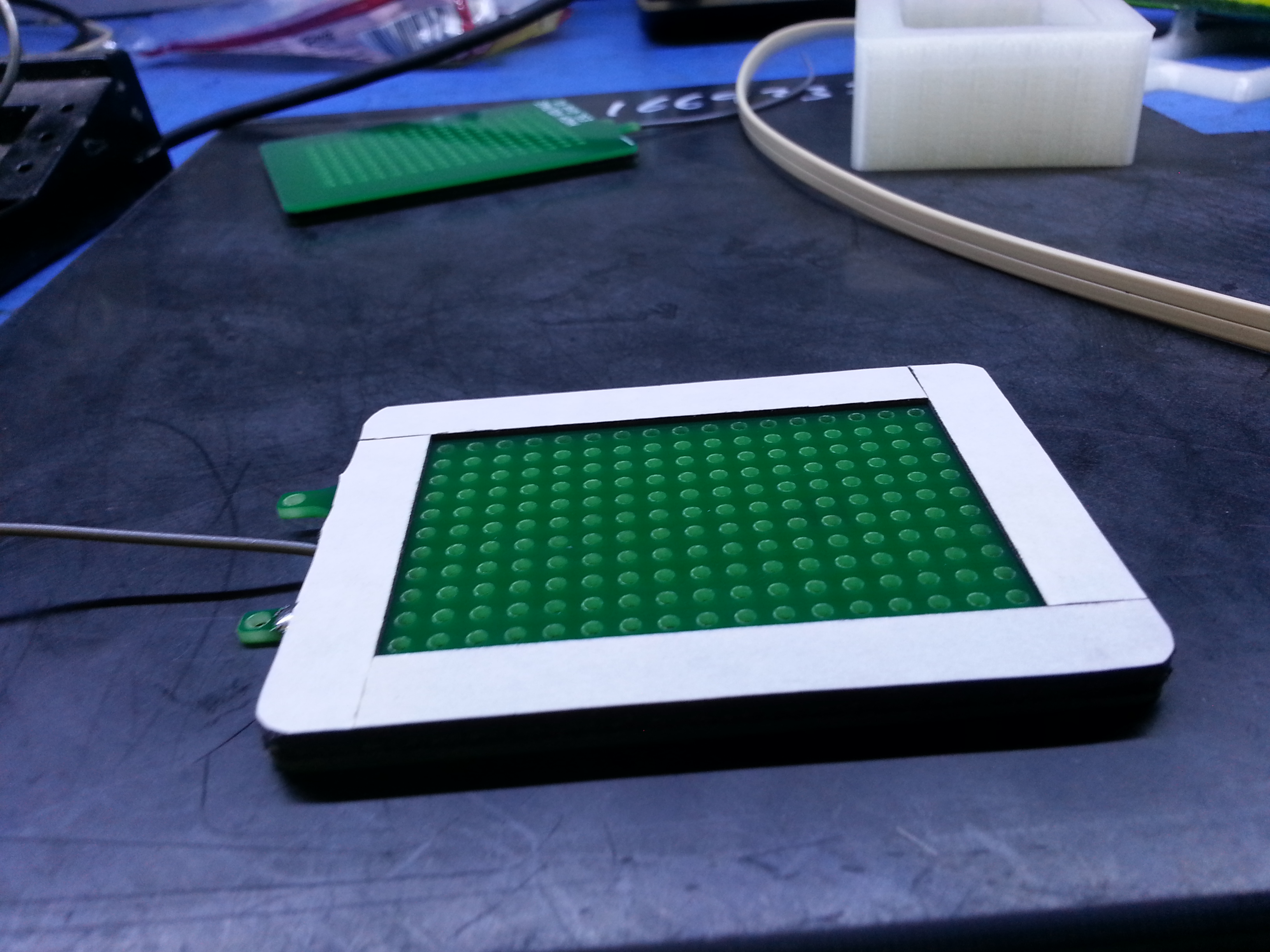
Finally, I stuck the grid with tape and wire down onto the plastic sheet. I did two sets at once, one for each ear. Once the tape was stuck, I cut around the grid with a razor to free the Mylar I wanted from the sheet. The final speaker is a sandwich, containing:
Grid, double-sided tape, wire, graphite-side of Mylar film, double-sided tape, grid

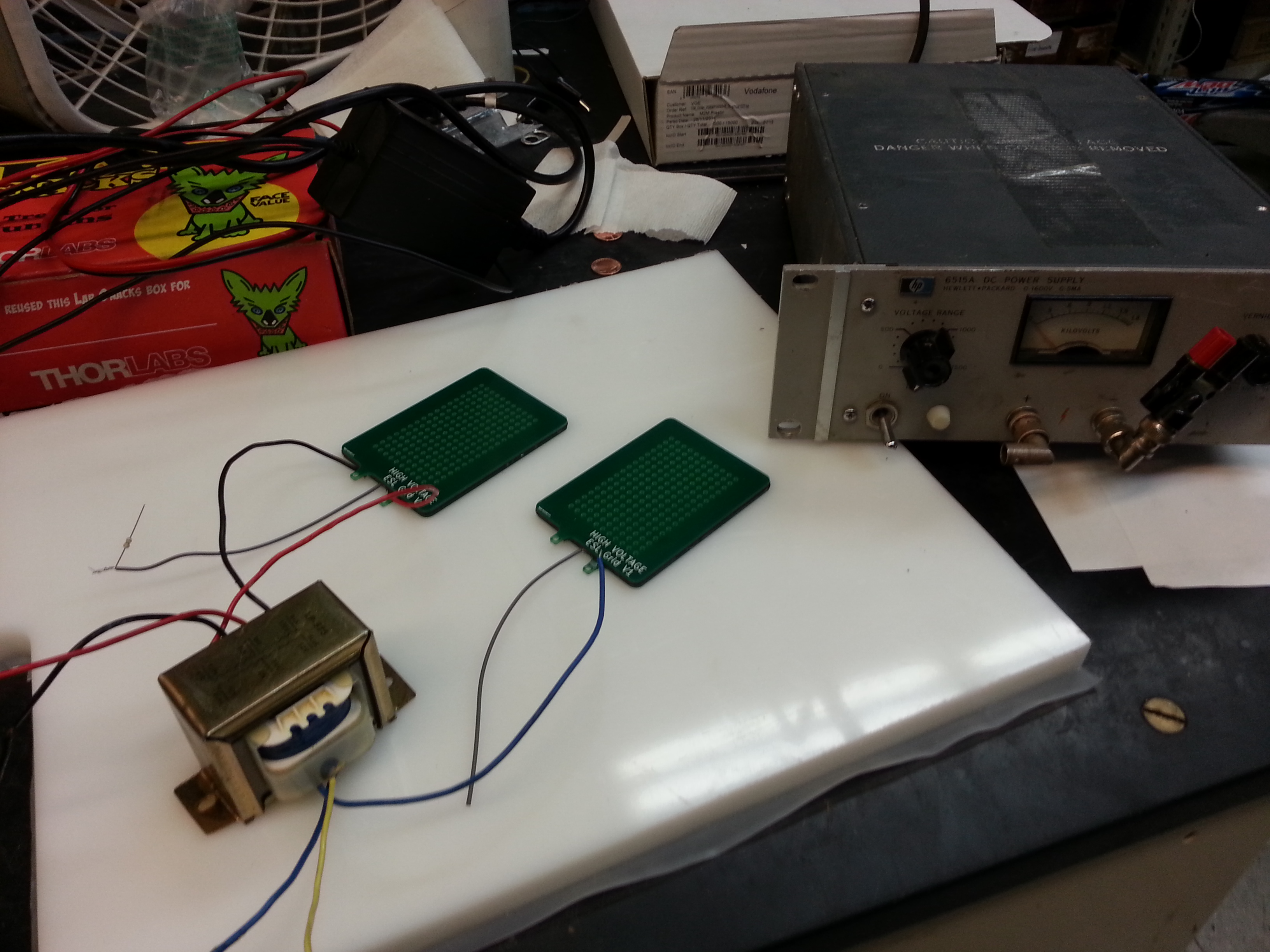
I tried the panels on a bench supply and a derpy old iron power transformer running in reverse to boost my audio signal to hundreds of volts, and to my surprise, I heard sound!
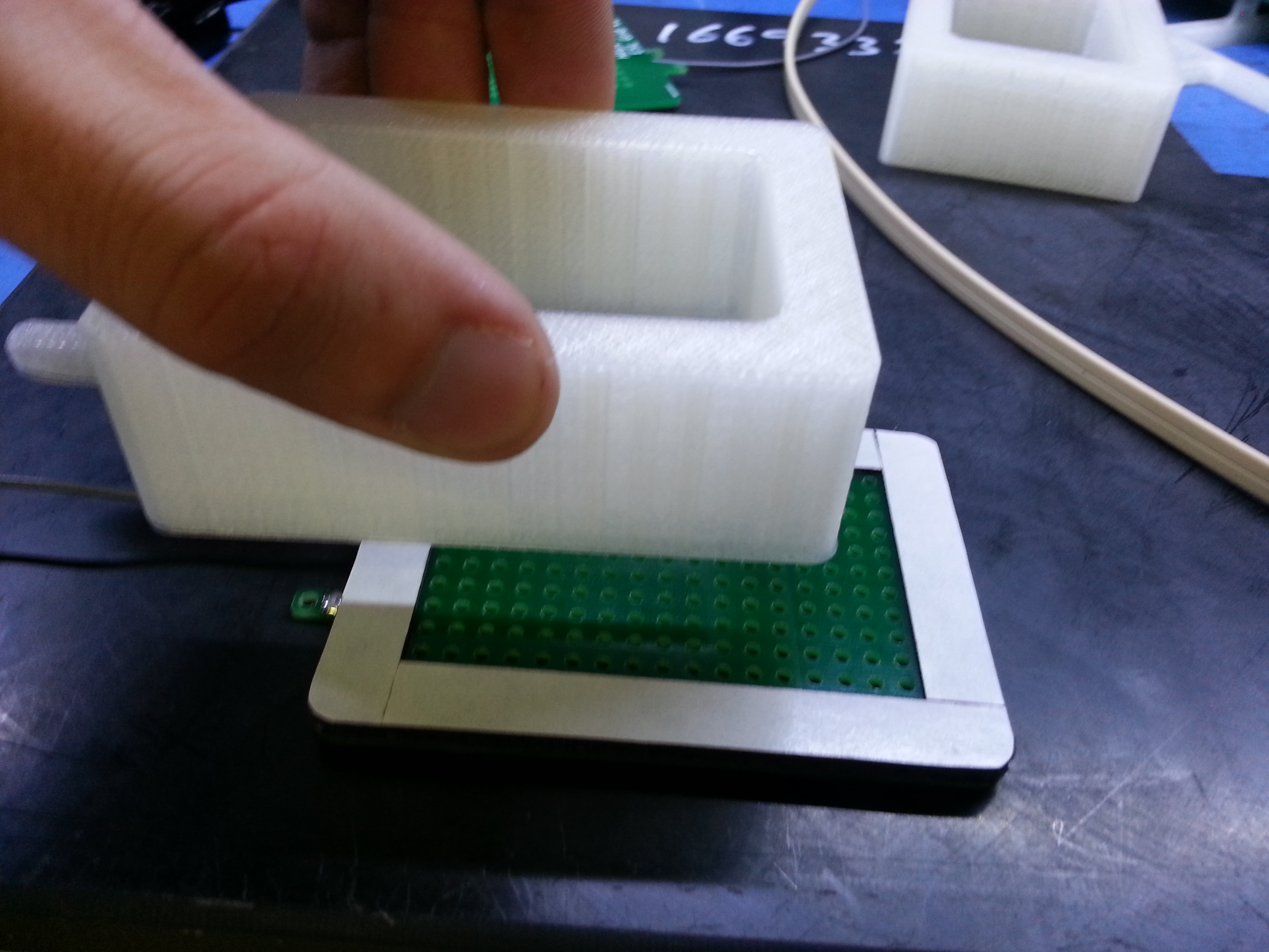
Finally, I 3D-printed a test enclosure and taped it to some headphone band, and made earpads from socks. The rest of the images show this process.

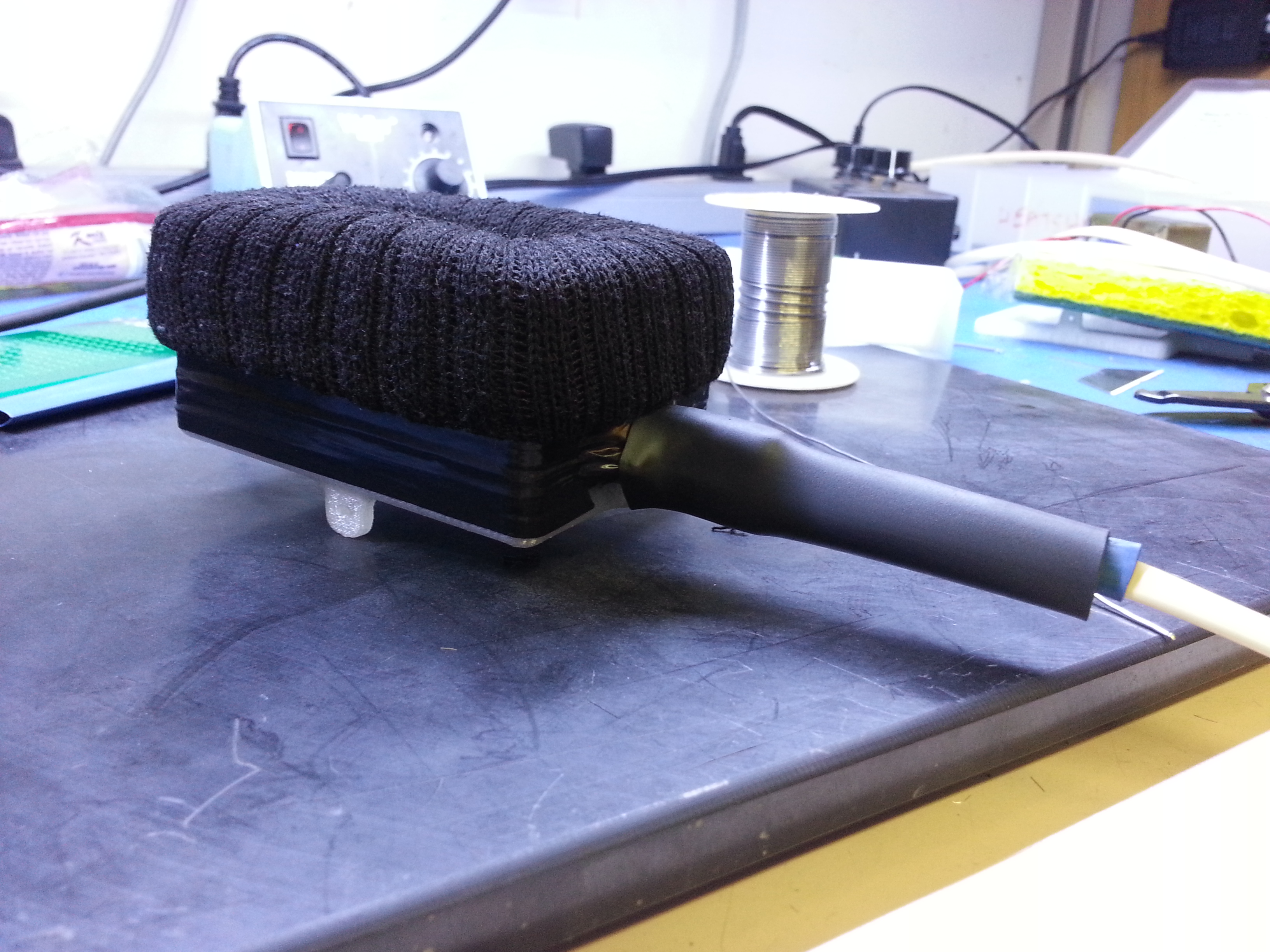

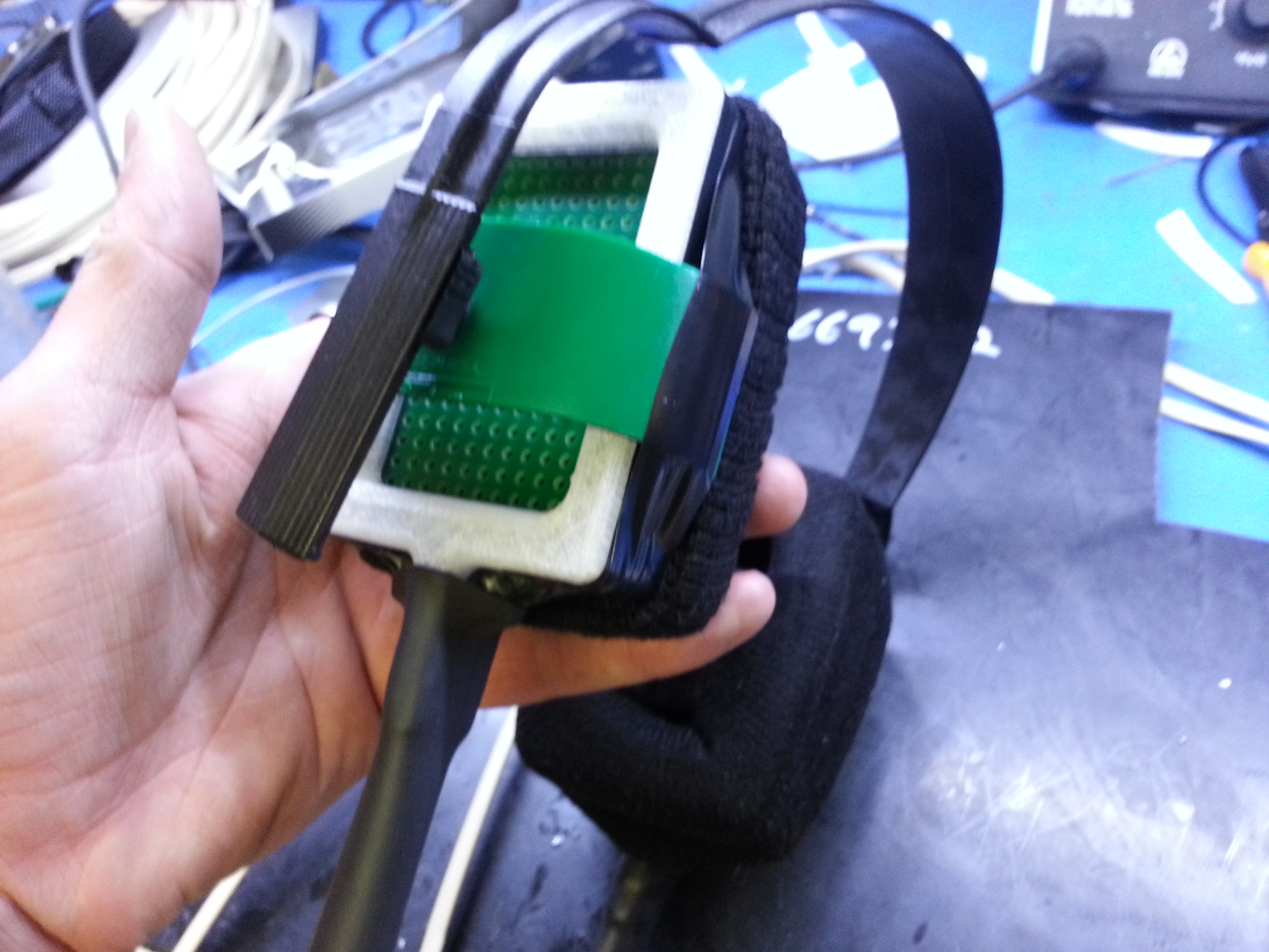
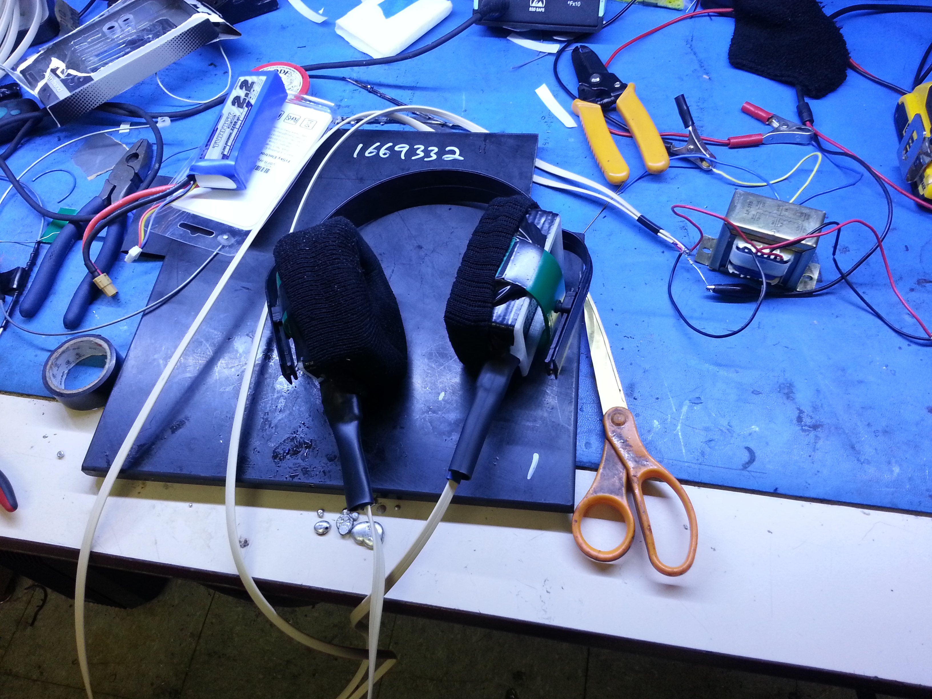
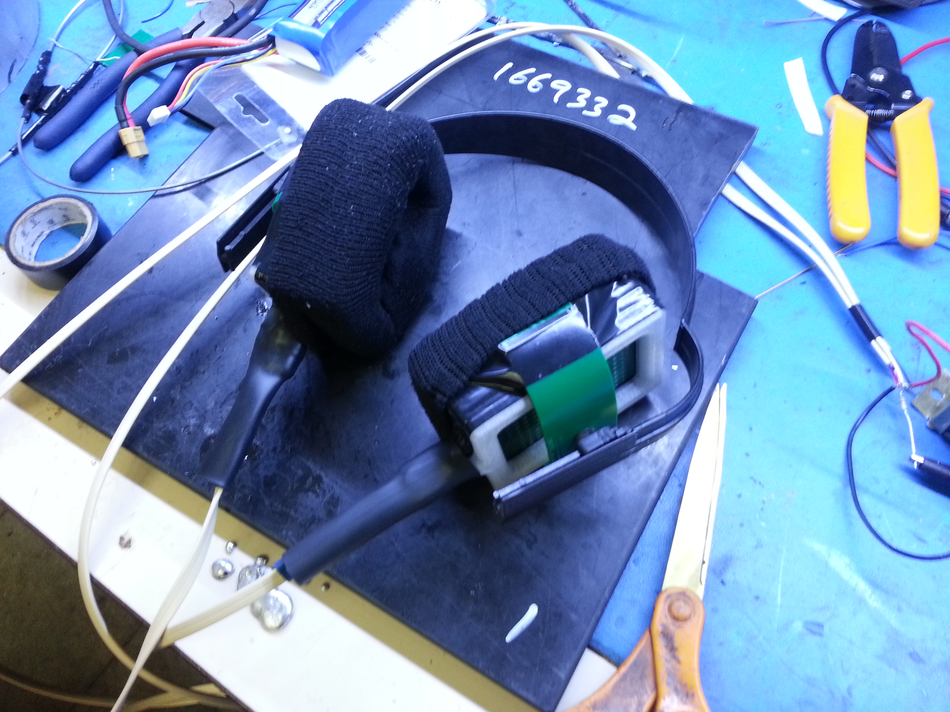
Happy high-voltage listening!
