This is a super-quick mostly-picture blog of my team’s 6.013 Electromagnetics class final project! We started work on this project by building and testing directional couplers and power splitters, which would allow us to split the RF amplifier output into transmit and reference.


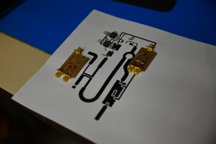
In order to make more exact prototypes, we used a small CNC router with an engraving bit. This allowed us to cut precise test patterns in the exact material we would be using.

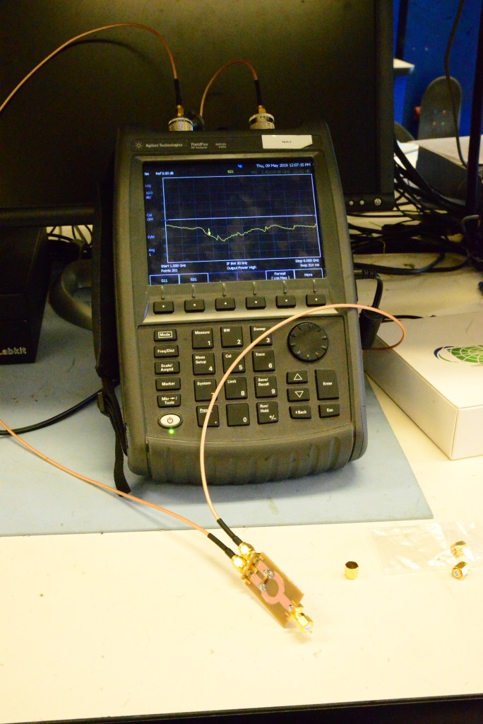
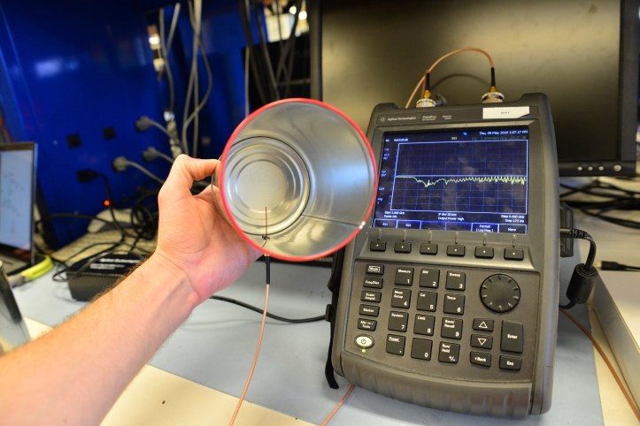
In addition to a board, this radar would require two directional antennas. For these, we made “Cantennas” and tuned wire length/position for best impedance at our desired 2.4GHz operation.
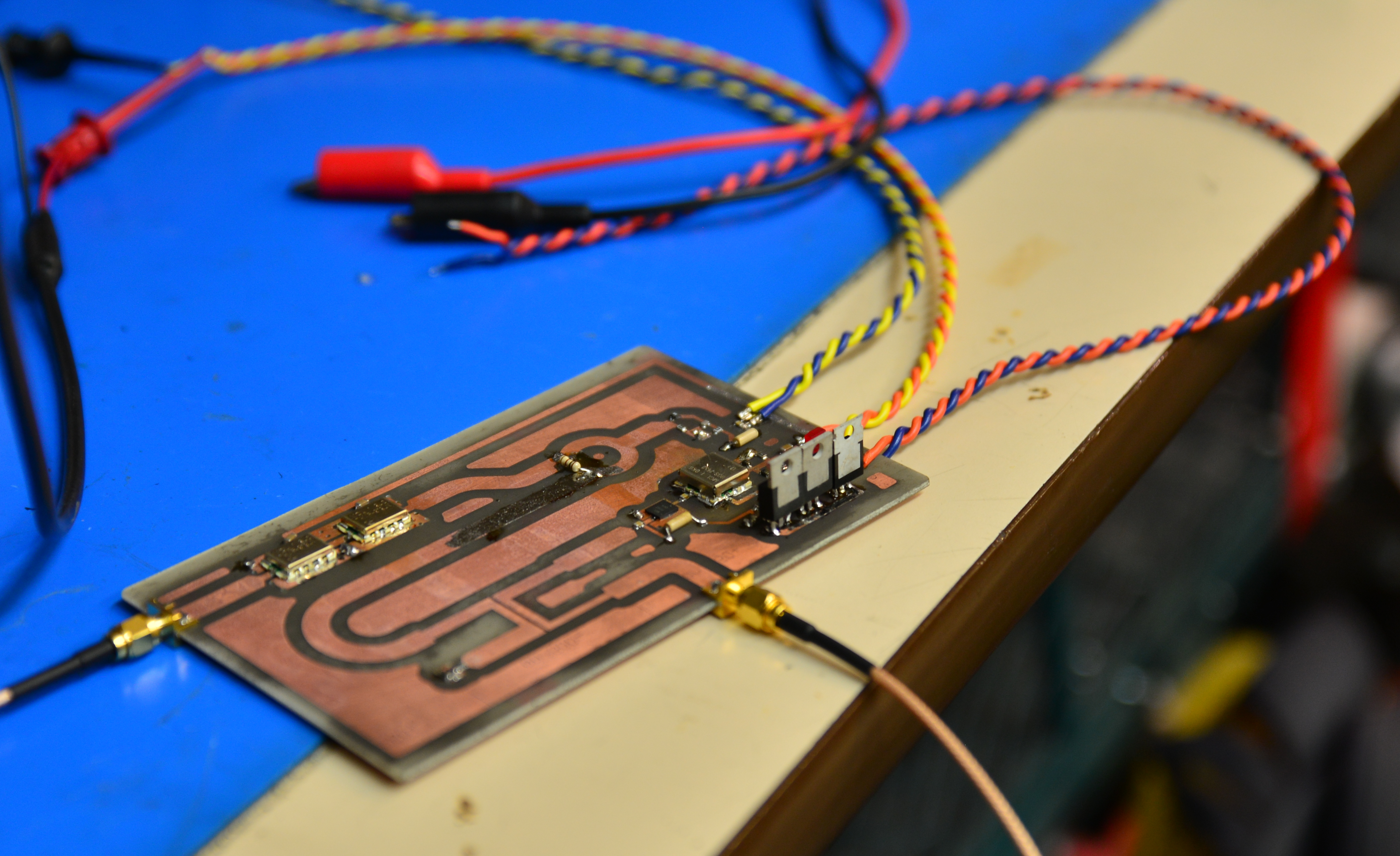
After testing, we laid out a board in KiCad. This board was single layer for ease of fabrication, and included both the directional coupler and the power combiner as copper geometry on the board.
We used toner transfer + etching for creating the circuit board. This process is shown in the next 4 images.


After this, I drilled holes for all of the connections to the bottom ground plane.


We populated the board using a hot-air reflow station.


Now a radar depends on having a good reflected radio wave off of the target object. In order to test the radar, we constructed a corner cube out of foam and aluminum foil. Corner cubes have the awesome property that any incoming wave reflects directly towards the source, regardless of the cube orientation. This makes it an easy, reliable target for testing.

This final picture is an oscilloscope trace seen when the corner cube is moved. This envelope is the beat between the reference 2.4GHz, and the reflected, Doppler-shifted frequency (2.40000001GHz or however fast you are moving).

Finally, here is a video of the radar in action!
