When driving a brushed DC motor from a DC power source such as a battery, you need some way to vary the amount of power that goes from the battery to the motor. People almost always do this using a switching converter (just turn the motor on and off all the way, but do it really fast so that nobody notices).
Additionally, brushed DC motors have inductance, meaning they don’t want to suddenly drop to zero current. Because of this, we need a “freewheel diode” across the motor in order to allow the motor current to freely recirculate while the low-side transistor is off. Conveniently, an IGBT half-bridge has body diodes on both transistors! This means we can short the gate of the high-side IGBT, thus turning it into a diode. We will use the bottom IGBT as expected.
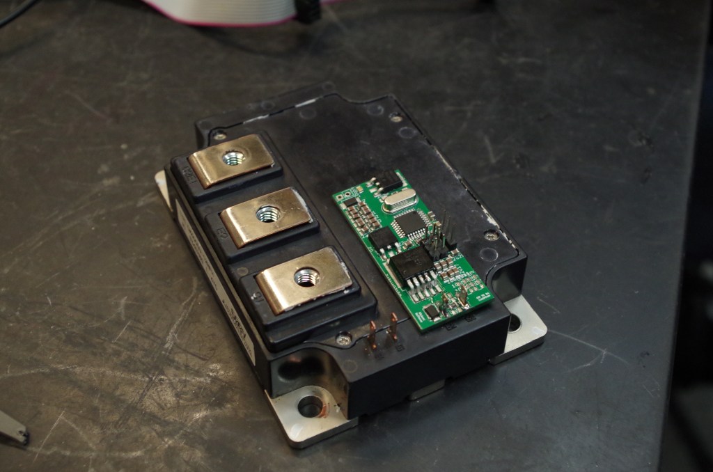
I designed and made a tiny logic board that would turn one of these half-bridges into a motor controller. It has an Atmega328, and an extremely large 30V, 30A gate driver to deal with the huge gate charge in the IGBT.
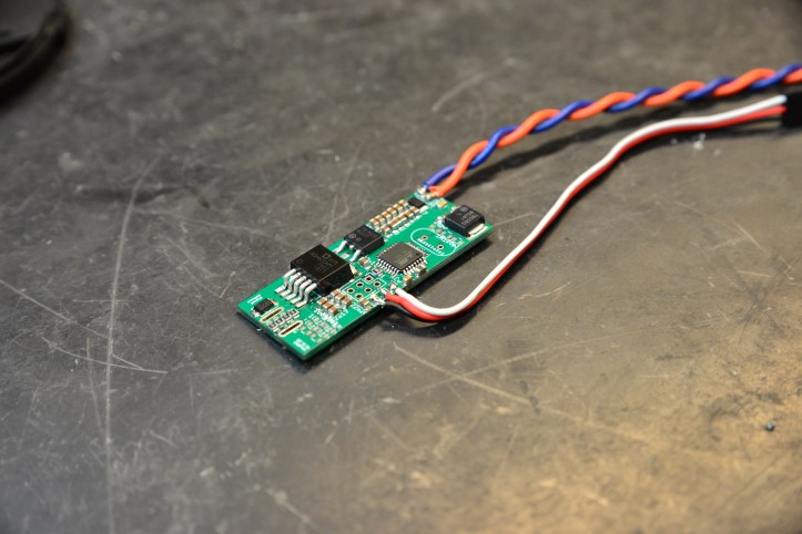

Once I had the boards made, it was time to solder one to an IGBT module and program/test it. I had help from a super awesome guy Jared on programming the Atmega. Here are some pictures from the assembly and testing:

Notice during testing we do not have any capacitor across the bridge. This is because if we mess up, we don’t want tons of fast energy storage waiting right there to blow up our devices. Once the testing is successful, we will bolt a film capacitor directly across the IGBT leads.

In final testing, we used a bench supply to simulate a battery, a CIM motor as a test load, and a servo tester as an input. This all worked wonderfully, as confirmed on the oscilloscope. After this, we soldered/glued everything down and called it good!
